| Total n00b's guide: NES controller mod to use on DC |
|---|
All right, so you've decided to mod a NES controller to play on the DC. When I first made one of these, I followed Marvin's tutorial and eventually, with some trials and tribulations, I got the controller working. It functions perfectly as far as I can tell. It was good to use a NES pad again.
This guide is designed for people with little to no experience in soldering/working with circuitry, as I was when I first attempted the NES-to-DC. A lot of pics and slow step-by-step instructions follow. A lot of this will be old stuff to many of you. Don't say I didn't warn you.
Oh yeah, usual disclaimer: I can't be held responsible for any damage you do to yourself, others, your controller ports, your controllers or your DC.
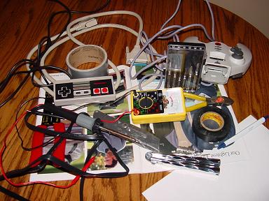
| You NEED the below stuff to follow this tutorial. Make sure you have it all. I included average prices as well, just so you know what this will set you back. | |
|---|---|
| Quantum Fighter Pad (there are other controllers that you can use, but I'm not getting into them. This one is the easiest to mod.) | $8 |
| NES controller (make sure it works properly before you do this all). | $3-$5 |
| Wire stripper. | $5 |
| Wire cutter. | $5 |
| Solder | $1 |
| Soldering iron - tapered tip a big plus, a pointed tip basically a requirement. | $8 |
| Electrical tape | $2 |
| 3mm Philips head screwdriver | n/a |
| Small prying instrument - like a small flathead screwdriver. | n/a |
| Pen and paper, or other writing stuff. | n/a |
| 9-pin/wire cable or higher. Cost can vary widely. Try to get a very thin cable, and at least 3 feet long. | $5 to $20 (very approximate) |
| The following are not needed, but they are generally very helpful. Prices included. | |
| Duct tape. This is borderline required unless you have really good electrical tape (or solder in a more difficult way - which I don't get into). | $3 |
| An assistant to hold stuff or a clamp. Prices vary on both. | n/a |
| Total Cost for all stuff: $35 | |
Odds are you already have some of it though, or can borrow it from a friend.
Ok, get your 9-pin+ cable and wire cutters. Cut off both ends of it - this may be difficult depending on how thick and well made it is. Now get your wire cutter/stripper. If you have a stripper that can actually handle a cable that thick, use it. I didn't, so I had to do it the hard way (that's a parallel port cable if you're wondering. It was the only free one of the right length I had, alright?).
Ok, just take your wire cutters and VERY VERY carefully cut a tiny bit of the wire. Do this cut about 6" back from the end of the cable. Cut just enough so that you won't cut any of the wires inside. I can't really give a better description then that. Just do it very slowly and carefully. After you've made a first cut, do it again in a different position till you've cut all the way around the cable. Assuming you did it well enough, you'll now be able to pull off the outer cabling and reveal the inner wires. If you didn't, you'll have to gradually cut in the places where you missed very carefully until you can pull off the plastic coating. Do this at both ends of the cable.
Ok, you've got a bunch of exposed colorful wires now. Cut them off and make friendship bracelets! Or not.. Yeah, not. Ok, unless you have that metal mash protective stuff (just cut it off with a sharp blade if you do) you're now ready to strip the wires.
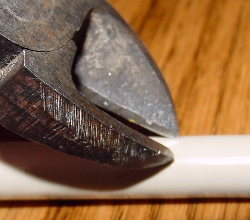
If you have a flat wire cutter like this one, cut into the wire insulation until it seems like it's almost at the metal. Then spin the cutter while holding the wire tight, and pull off the insulation. If you have a different one, you're on your own, since I don't have one. Just cut into the insulation as far as you think you can and spin your cutter. This is pretty easy, just don't cut deep. It's better to have to repeat a couple times then to cut through the wire. If you have more then 9 wires in your cable, I'd recommend cutting off the ones that you won't be using. Just so you don't get mixed up - and be careful you end up with the same 9 colors on both ends of the cable. I'd recommend using your multimeter to test a couple of the wires to make sure they aren't broken in the middle or something. I guess that's not very likely, but better safe then sorry.
Tinning is where you melt solder onto the wire to give it a fine tip and have a better electrical contact.
Oh yeah, grip the iron by the rubber part. Touch nothing metal.
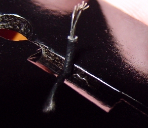
Ok, plug in your soldering iron and wait about 15 minutes. Get your solder out and pull it till you have a straight piece. Now push the iron tip into the end of the wire. Now push the solder into the wire slowly and let it melt evenly. Make sure when the metal cools the wire has a tapered tip, with no odd things sticking out. If it does, carefully push the iron into the metal again and flatten it. Repeat this 17 times (once for each wire end, not 17 times more on this same wire. DUH).
The Quantum pad is great because there is already a separate wire for each button. You just have to solder wire to wire, which is easier then just soldering on a board (and can be stronger in some circumstances).
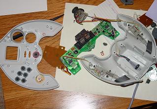
To begin, unscrew all 6 screws from the back of the pad and put them in a labeled baggy. Just make sure you can find them again later. Now open up the controller slowly, and you'll notice a bunch more screws holding the guts of the controller to the front part of the controller. Unscrew all this, and unscrew the things holding the analog stick in. Pull out the analog stick, but make sure you know which direction is up. Right UP with a sharpie on it, as you'll be putting the analog stick back in (the controller will still partly work - the analog stick, L and R, and the B button.). Next, you'll see a couple wires going to a metal circle glued into the plastic. Just snip these wires - the circle thing is a watch battery so the controller can remember programmed moves. Obviously, you won't need it anymore. Also unscrew the VMU slot thing, and pull it off and set aside. Snip all the wires for the d-pad, cutting near the d-pad board. Do the same for where the start button is.
Put all the screws and the black piece which held the analog stick in place in a ziplock bag.
You should now be able to remove the boards from the front part of the controller shell. Do so carefully so none of buttons fall out. Set aside the front part carefully.
Ok, here is the layout and which wire equals what.
| For the d-pad, position is relative to the board sitting in place in front of you. | |||
|---|---|---|---|
| Color | Position | Arrow Direction | Solder point # *Down from top left |
| Yellow | Left Most | Up | 1 |
| Orange | Left Most | Right | 2 |
| Red | Left Most | Left | 3 |
| Brown | Left Most | Down | 4 |
| Black | Left Most | Ground (power, basically) | 5 |
| For the middle buttons.. | |||
|---|---|---|---|
| Color | Position | Button | Solder point # *Down from right side |
| Yellow | Middle | Start | 2 |
| Cyan (blue) | Middle | Ground (power) | 1 |
| Right position - the main buttons | |||
|---|---|---|---|
| Color | Position | Button | Solder point # *Up from bottom right |
| Black | Far Right | Ground | 1 |
| Brown | Far Right | A | 2 |
| Red | Far Right | X | 3 |
| Orange | Far Right | B | 4 |
| Yellow | Far Right | Y | 5 |
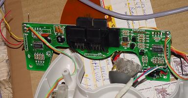
The picture above should be what you pretty much have now. Just leave the triggers alone
Ok. Look at the board for the controllers. What you're going to do here is snip the wires except for orange and black. Orange is for the B button, and this is the only button that the NES won't have (discounting L and R anyway), so we're going to leave it there. That way You'll be able to do all of NesterDCs cool little functions. So.. CAREFULLY snip yellow, then separate orange from red by pulling them apart CAREFULLY and making sure not to pull the wire at all away from the solder point (it isn't that delicate, but you could pull it out of the board. That would be bad). Then snip red and brown. So you now have a button board of which all buttons are disconnected except power (black) and orange, for the B button.
Pull apart the 5 d-pad wires (including ground) and the start button wires and button wires. Strip these wires the same way you did the cable wires. Ok, you are now just about ready to solder. Plug in your soldering iron, put the board flat with the wires you are going to solder onto bent back.
It should look like this:
You'll have to wait about 15 minutes for the soldering iron to heat up.
Make a list of which color wire in your 9 wire cable goes to which. I reccomend doing it on normal paper and keeping the list handy.
Mine has a color, what it is on the quantum pad, and what it is on NES. Obviously, they should be the same with the exception of X on the Quantum being B on the NES, and Y on the Quantum being select on the NES. Keep this paper handy and don't mess it up.
Now, take the metal of your chosen color and match it with the equivalent color for that button/direction on the quantum pad. Put the wires on top of each other, and gently press the iron into there for a second or two. Once they're bonded, I'd recommend getting a second drop of solder, rolling over the bonded cable, and putting the drop there and making a stronger bond. Now take a small piece of electrical tape and wrap it around the exposed metal. Then take a small piece of duct tape and wrap it around it as well. Make the wrapping tight so the bulge is small.
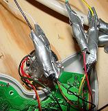
Sorta like that, ok?
Do this until you've soldered all the wires to their proper points. You only have to do ground to one of the multiple grounds - I recommend doing it to the one by the d-pad directions.
Now that you're done, reassemble the controller.. This is trickier then it sounds. You'll have to carefully put the duct taped wires into a good enough position so the controller will be able to close. Also remember to screw the slightly functional (just one button now, B) button board back into place. And put the analog stick (FACING THE RIGHT WAY) back in. You'll lose VMU slot 2 most likely, as their won't be enough room with the cord fed out. No big deal though, as VMU slot 1 will work fine. Oh yeah, you can not put the VMU plastic slot holder thing back in as it's to big and prevents wires from coming out the top. Now screw the controller closed, and duct tape the wires strongly to the plastic frame in a couple places. This is to prevent the solder points from being tugged out. Congratulations, the host controller is now done!
Depending on how good you are with a soldering iron, this will either be relatively easy or challenging and frustrating. The first time I did this, I found it easy. The second time, hard. I don't know why.
Ok, first unscrew all 6 screws from your NES pad and put them in a baggy so ya don't lose them. Cut the 5 wires connected to the board and pull out the NES controller cable. Set it aside, throw it out.. Whatever, doesn't matter. I kept it just in case.. Ya never know.
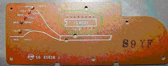
This is the back of the NES board, see the circled area? On yours there is a black thing called the IC. This should be removed. I'm not positive this is necessary or not - but do it anyway. To remove it, stick a screwdriver in between two of the metal pieces and pry apart. Do this to them all and pull off the IC. Now, I saw one person (Marvin) who had the wires done through the holes on the back. I couldn't get this to work.. SOOO, we'll be doing it on the front of the board. Not quite as neat, but it works just as well.
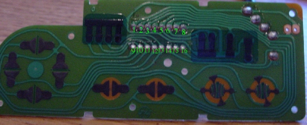
| See the numbers? Here is what they are.. | ||
|---|---|---|
| Left | = | 11 |
| Up | = | 13 |
| Right | = | 10 |
| Down | = | 12 |
| Start | = | 5 |
| Select | = | 6 |
| B | = | 7 |
| A | = | 16 |
| Ground | = | 9 |
You should double check these anyway. Look at the two green paths that come out of each button. One goes into a pathway where several meet. The other pathway is unique to the button. Follow this pathway to the solder point. Alternately, you could touch one point of the multimeter to the unique part of the button and the other to solder points til you get one match which will max out on the multimeter. Make sure the multimeter is set to OHMs.
To solder onto these: find the corresponding color wire, push the iron a bit into the metal of the point and then after it has turned a bit liquidy push the wire into the point. This is harder then it sounds for most people. You pretty much have to learn how to do this by trial and error. Good luck on it. Do the previous steps for all the wires. When you're done, get out the multimeter set to OHMs. Touch one point to a solder point, and the other point to a corresponding point. If you get full power (multimeter arrow moves all the way over to the other side) you have a wire crossover. To uncross them drag the soldering iron point between the points slowly and carefully. It's hard to do and you'll probably have to do this a few times.
Make sure to test for crossovers on ALL adjacent points. Otherwise you'll get weird effects, like at one point for me right equaled left and left also equaled left. It is also possible, though unlikely, that a crossover could damage your Dreamcast - blow a port.
Now, put the board back in being careful to run the 9 wires out of the slot the NES cord used to be. Put the shell back on, and screw it back in. You might have to apply pressure to get it to fit as the wires take up space.
Ok, you're done!
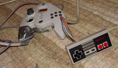
Here is my completed controller..